Mark of Zero Logo
Main menu
   You are here: /Home/Plans/PWM v2.1

Get my instant news
alerts now on Twitter!

Donate Bitcoins

K&J Magnetics, Inc World's strongest magnets

PWM Parts List          

The Zero Fossil Fuel Constant Current PWM v2.1

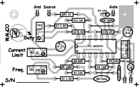
This is a slightly modified version of the first PWM. The basic circuit is the same. Some component values have changed. And it's laid out specifically to fit in a Velleman G106 sealed die cast aluminum enclosure measuring 4.5" L x 2.5" W x 1.25" H. Bud and Deltron also make very nice die cast aluminum cases.

Related Links

Circuit description:

U1 is a LM324N quad op-amp. U1A and U1B form a triangle wave generator. The output voltage swing is approx. 1/3-2/3 Vcc. The output is fed to comparator U1C which turns it to square wave based on the threshold voltage at pin 10. The duty cycle threshold is set by VR1. R6 and R7 are calibrated to give full range duty cycle adjustment of VR1. The voltage reference for R7 is normally held at Vcc by the output of current limiting error amp U1D. Gain is set at 1000 (subject to change depending on how stiff I want the current to limit). Any time the source of Q1 draws current a voltage drop occurs across R12. 80 amps will give 120mV, the max setting on VR3. If the voltage drop across R12 exceeds the preset value of VR3, the comparator drops the PWM duty cycle until the average is just less than the preset value. C4 ensures that the current limiting is average not peak.

R12 is just a 6" piece of #14ga stranded copper wire. The leads are connected to the Source of the MOSFET, AT THE SOURCE TERMINAL, and to the common ground, AT THE COMMON GROUNDING POINT. Also, the PC board terminal at the junction of C4/VR3 connects directly to the common ground and the PC board terminal for R10 connects directly to the MOSFET Source terminal. These steps are very important to observe as unwanted oscillations and instability can occur.

Click here for the detailed parts list.
Click here for the adjustment procedure below.

Click here for video play lists of the step by step assembly procedures.

Schematic image. Click to enlarge
Click image to enlarge


Click image to enlarge


I get a lot of email asking how to adjust this thing without an oscilloscope. To be honest, the only reason I use a scope is to adjust the frequency to precisely 2.5KHz and observe visually when the PWM starts to limit. The frequency range is 1KHz-10KHz. The frequency of the PWM is far less important than most people think. More is not better. In fact, I'm considering changing the range to 500Hz-5KHz by changing the value of C1 from 0.022uF to 0.047uF. Usually the VR pots ship adjusted to the mid point. By default your PWM should operate around 2KHz (1KHz if you change C1 as described earlier). There really should be no reason to change it unless there are some resonant acoustic properties of your cell that you'd like to experiment with. In that case you can just adjust the frequency pot VR2 by ear.

To set your PWM to limit current you will need some way of measuring the large current being drawn by your load. You can buy ammeters that have external shunts for this purpose for around $30, just the shunt alone if you have a digital multi-meter for about the same price, you can build your own shunt as I've shown in video #43 for mere pennies, or you can get a clamp on DC ammeter as I did for around $80 from Harbor Freight.

  • First, adjust the electrolyte concentration of your cell to draw the amount of current you want it to draw at its coldest operating temperature from straight DC (without the PWM). Measure carefully as you do this so you will know what the concentration is the next time you have to flush the cell and refill. Otherwise all you should have to do is add distilled water to keep topping off your cell.
  • Pots are 20 turn. Start adjusting the PWM by turning the Current Limit pot VR3 and % pot VR1 fully CW. Just keep turning until you start to hear them click or until you're certain you've turned them at least 20 turns. They won't break if you try to go beyond maximum rotation.
  • Connect your PWM to the cell, apply power and monitor the current. As the cell warms up it will start to draw more current.
  • Once the current exceeds where you want the cell to operate, rotate the Current Limit pot VR3 CCW until it settles to the operating current you want. As the PWM starts to limit current you will hear it start to whistle.

Done!

As the cell heats up, peak current will rise but duty cycle will fold back an equal amount to keep the RMS current constant.

You should also view my video #119 prior to operation.

Have fun!

    About Contact Legal        
Site design by Zero Mark of Zero logo Trademark 2008 ZeroFossilFuel. All rights reserved.