| You are here: |
|
- Home
- FAQ
- Zero Labs Store
- Plans & Schematics
- Tell-A-Friend
- Latest News
- Hall of Fame
- Links Page
- Event calendar
- Product reviews
- Alt-Nrg Forum
- Video Vault
- Zero Live!
Get
my instant news
alerts now on Twitter!
![]()

![]()
|
|
|||||||||||||||||||||||||||||||||||||||||||||||||
|
|
|||||||||||||||||||||||||||||||||||||||||||||||||
|
|
|||||||||||||||||||||||||||||||||||||||||||||||||
|
|
|
||||||||||||||||||||||||||||||||||||||||||||||||
|
|
|
||||||||||||||||||||||||||||||||||||||||||||||||
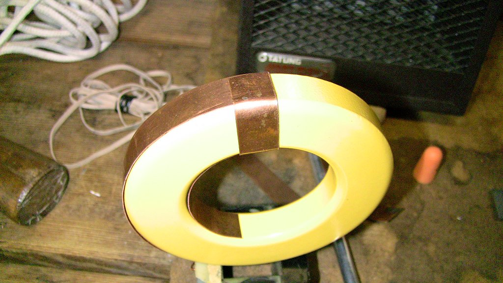
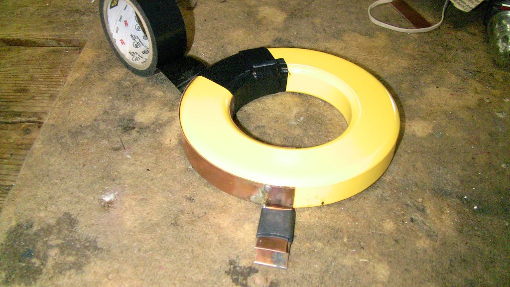
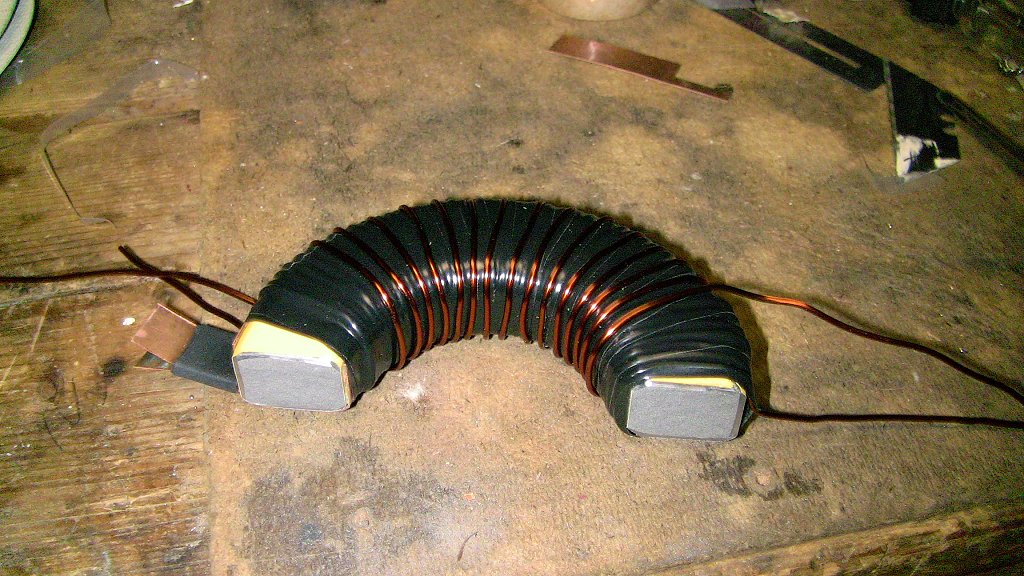
| Update 11/29/11 - Had difficulty achieving any form of resonance per the tuning procedure provided by Wesley found at http://freeenergylt.narod2.ru/aidas/ Thinking it might be related to the difference in ferrite shape, today I went dumpster diving and salvaged an almost identical ferrite to Aidas from a Dell CRT computer monitor. Only thing is mine is smaller 75mm at the widest point. His was 111mm at the widest, 75mm at the smallest point. Overall mine is about 35% smaller but very close to the same shape. The effect I expect it to have is to raise the resonant frequencies by about the same proportions unless I add 35% more capacitance to tune them to the same frequencies. We shall soon see. Below is tonights progress. | ||||||||||||||||||||||||||||||||||||||||||||||||||
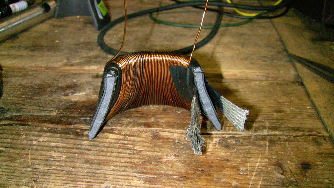 Inside view of 1T 3/4" wide copper braid primary #1 with 50T 20ga primary #2 on top |
 Outside view of 50T primary #2. |
 Outside view of 15T 20ga primary #3 on top of 50T primary #2. |
||||||||||||||||||||||||||||||||||||||||||||||||
 Inside view of 15T promary #3. |
 2nd ferrite half with 22T 20ga bifilar secondary output. |
 Inside view of bifilar output. Notice once again how the wire pairs are side by side. This creates a distributed capacitance between the two windings that stores exponentially more energy than std coils. |
||||||||||||||||||||||||||||||||||||||||||||||||
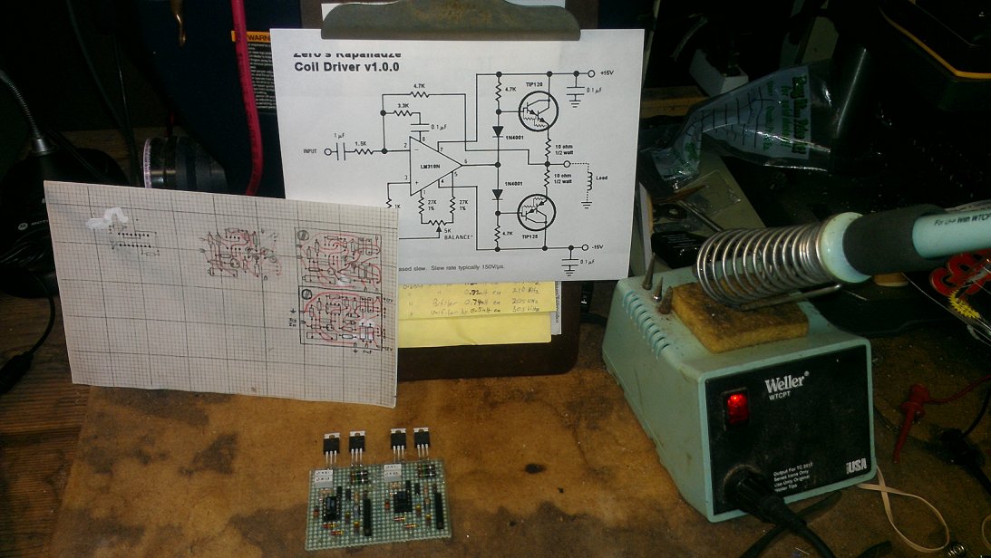
 Breadboard assembly showing the finished cone coil, fkyback, driver & 3ch convergence amplifier chip. |
 Tested and working schematic. |
 Finished prototype board layout. Click to enlarge and print. |
||||||||||||||||||||||||||||||||||||||||||||||||
 Pics of the board assembly process. |
 Top
view of completed 2ch driver bd. Note that I did take some creative
license with less critical component values. Power transistors are
alligned on one edge to facilitate mounting to a heat sink. Top
view of completed 2ch driver bd. Note that I did take some creative
license with less critical component values. Power transistors are
alligned on one edge to facilitate mounting to a heat sink. |
 Bottom
view of the board showing how I interconnect the components to the
bd layout. If it works as hoped, this allows it to be translated to
an etched PCB with virtually no modifications at all. Bottom
view of the board showing how I interconnect the components to the
bd layout. If it works as hoped, this allows it to be translated to
an etched PCB with virtually no modifications at all. |
||||||||||||||||||||||||||||||||||||||||||||||||


| Contact | Legal |